Automatic planning
Plan and document a smart home installation: step by step with KNX
Step by step from the automation system to the dossier: modules in the distribution board, push buttons and motion detectors on the channels, channel plan for the board door, terminal plan, functions by room, lines with bus budget, draft or final and team work – for KNX, Niko Home Control, Loxone, Shelly, Sonoff or vendor-neutral planning. For KNX also addresses and files for ETS.
 AuthorStephan Behm
In the Smart home mode you plan and document building automation from the same project as the floor plan and the single-line diagram: choose the automation system, put modules in the distribution board, assign lights and shutters to channels, link push buttons and motion detectors, check the lines. This produces the channel plan for the board door as PDF or CSV, the terminal plan, the functions by room, topology and quantities, individually or as a Domotica dossier in draft or final. It works for KNX, Niko Home Control II, Loxone, Shelly, Sonoff and vendor-neutral planning. Programming the devices stays in the manufacturer's software.
The guide follows a KNX example: a fictitious Belgian apartment with seven rooms, a push button in every room, a shutter at every window and motion detectors in the hall and the bathroom. For KNX two sections are added at the end: proposed addresses and files for ETS. The whole story is told in the blog post Documenting a smart home installation with a KNX apartment. Status, version and data hash of the documents are described in Plan KNX: push buttons, channels and quantities.
What do I need before I start?
| Prerequisite | Why |
|---|---|
| Floor plan with rooms | Rooms place control points and group addresses on the right floor |
| Lights and shutters placed | They are the loads you assign to the actuator channels |
| Circuits with protective device | Every switched load needs its circuit breaker in the single-line diagram |
| Distribution board with free DIN rail | PlanElec puts the automation modules there |
| Project role with edit rights | Viewers see the planning but cannot change it |
How do I choose the automation system?
- In the mode bar on the left, choose Smart home. The Channels panel opens on the right.
- In the Automation systems bar, click your system: KNX, Niko Home Control II, Loxone, Shelly Pro / Plus, Sonoff or Generic / configurable. PlanElec then offers the modules, control points and line types of that system. In the example it is KNX.
- You can tell it worked from the Domotica planning steps: step 1 System shows Active.
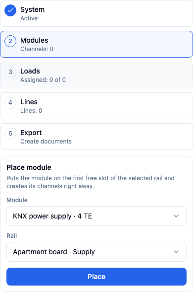
The five planning steps are System, Modules, Loads, Lines and Export. Each step shows its status, for example “Channels: 12” or “Assigned: 17 of 17”, and takes you with one click to whatever is still open. You can also choose the system in the project metadata under Building automation; the effect is the same. A project can carry several systems.
How do I document the distribution board with modules, rails and terminals?
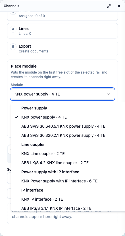
- Below the planning steps, open Place module.
- Choose the template under Module. The list shows the modules of the chosen system, grouped by device family; for KNX, for example, power supply, line coupler, IP interface, switch, shutter, dimming and heating actuators and binary inputs, vendor-neutral and as ABB i-bus types with order numbers.
- Choose the DIN rail in the board under Rail and click Place.
- PlanElec puts the module in the first free slot, creates its channels and assigns power supply, bus devices and control points to the system's line, for KNX the default line 1.1. The message “… placed, channels created.” confirms the step; Place another module opens the form again.
In the example apartment, the rail “KNX 1” holds an ABB SV/S 30.640.5.1 (640 mA power supply), an ABB IPS/S 3.1.1 (IP interface) and an ABB SA/S 12.16.2.2 (12-fold switch actuator); “KNX 2” holds a vendor-neutral 8× shutter actuator and a 4× dimming actuator. The cabinet shows the ABB types in the manufacturer’s style, with red and black bus terminals.
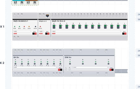
In the distribution board editor (Distribution board panel) the automation modules sit together with the main switch, RCDs and circuit breakers. There you maintain terminal blocks and wiring. The terminals of the automation channels, with strips, targets and bridges, are maintained in the Channels panel under Terminal plan. Order numbers and bus current of the ABB types come from the manufacturer’s data. Check them against the actual datasheet before ordering. ABB is a trademark of the ABB Group; PlanElec is not an ABB partner.
How do I plan push buttons and motion detectors?
- Close the panel so the floor plan is free, and open the catalog.
- In Control points & sensors, choose a Push button, Double push button, Quadruple push button or Motion detector and click on the wall or ceiling in the room.
- The floor plan shows the symbol in the room. Bus control points end up on the line of their system (line 1.1 for KNX) without any further step.
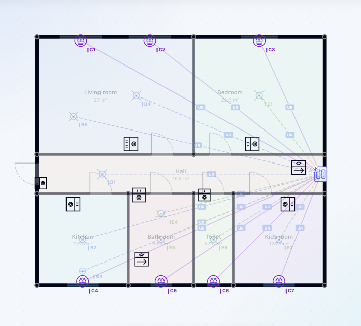
When addresses are proposed, motion and presence detectors get two objects of their own: a switch object (DPT 1.001) linked to the switching group address of the light channel, and a brightness object (DPT 9.004). A push button gets no group address of its own; its buttons refer to the group addresses of the channels they operate.
How do I assign loads and push buttons to the channels?
In the Channels panel, choose the Channel matrix view. The channel table shows one group per module with board, rail, slot, type and line, and below it every channel with Channel type, Loads, Room, Control points, Terminal, Protection device and Line / PA.
- In the Loads column, click + and choose the light or shutter. PlanElec offers the loads that match the channel type.
- In the Control points column, click + and choose the push button or motion detector.
- Repeat this for every channel. Room and protective device come from the project; you do not enter them twice.
Suggest by room distributes unassigned loads to free channels by room and channel type. Existing assignments are kept. Review the proposal channel by channel afterwards.
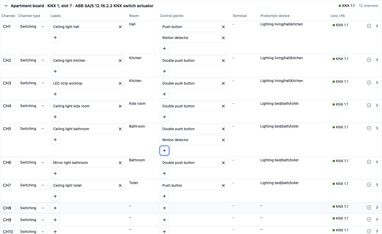
The right end of each row shows the channel’s finding. A check mark means no open planning data. An exclamation mark says what is missing, in the example “The channel rated current is unknown; check the device and enter its rating.” for the vendor-neutral dimming actuator. Other findings include a load assigned twice, a load without protective device, an unsuitable channel type or an overload. The findings are planning checks; the project’s AREI self-check stays separate. (The AREI, called RGIE in French, is the Belgian regulation for electrical installations.)
How do I check lines and bus budget?
- In the Channels panel, choose the Lines view.
- Click Assign unallocated devices if bus devices without a line are left. Add KNX line creates another line, Add area 2 another area. Each line has its own colour and carries its address as its name, for example “KNX 1.1”.
- In the line card, choose Power supply module and Supply capacity (mA), for example 640 mA.
- Enter the datasheet value under Bus current (mA) wherever you know it.
- Drag devices between lines, several at once via the checkboxes; without a mouse use Move to. Unlocked physical addresses follow the line.
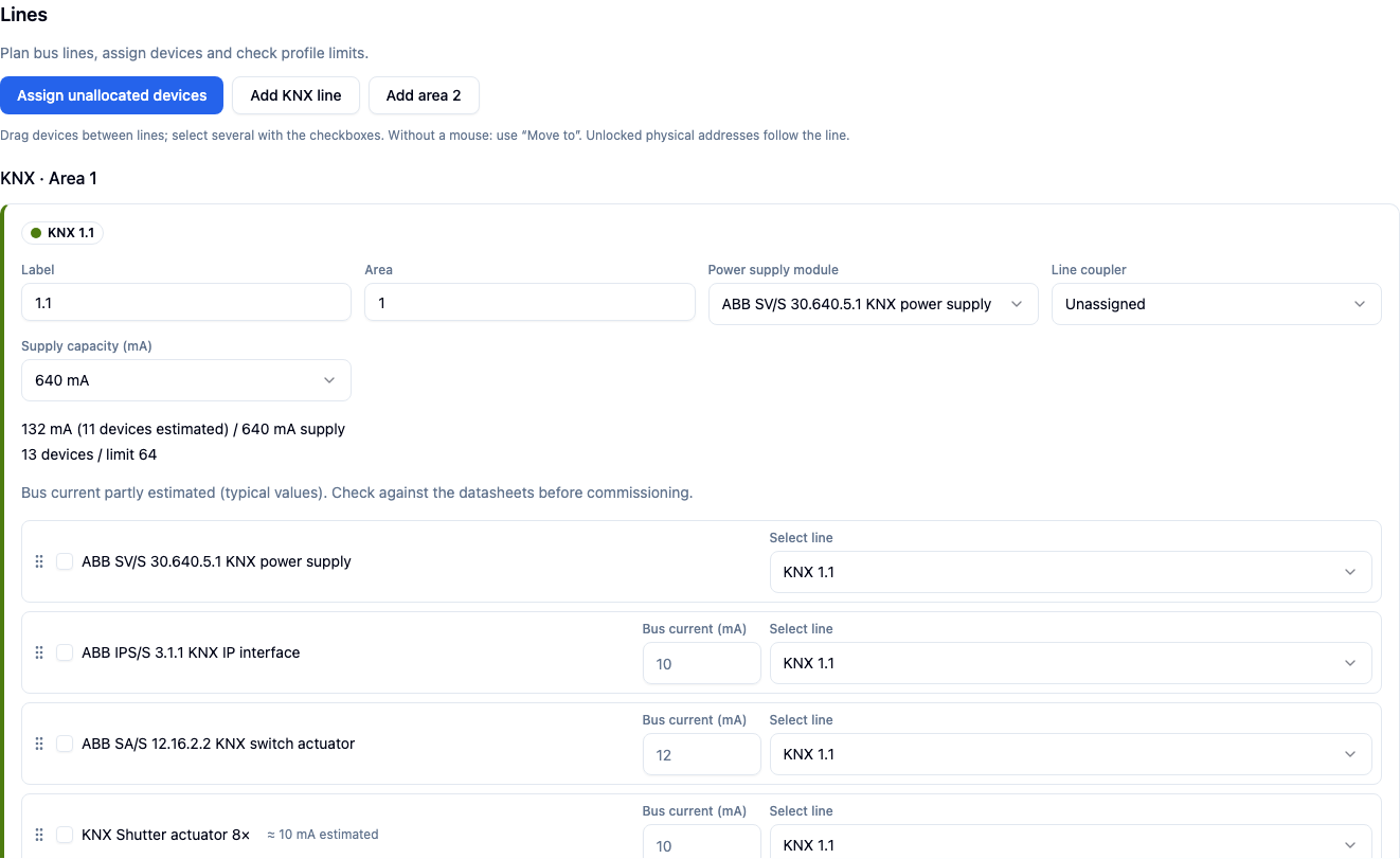
The budget shows the bus current against the supply and the number of devices against the limit of 64 devices per line. For values you have not entered, PlanElec uses typical values and marks them as “estimated”. Before commissioning, check them against the datasheets. A line is a logical planning state, not a measured cable route; you draw the bus cable on the floor plan with Route bus.
How do I create functions, scenes and central functions?
- In the Channels panel, choose the Functions view.
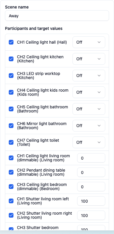
- Add scene opens the scene editor. Enter a name, for example “Away”, then choose the channels and their target value: on or off for switching, a percentage for dimming and shutters.
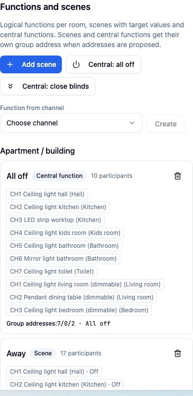
- Central: all off and Central: close blinds create the usual central functions in one click. Function from channel with Create turns a single channel into a function.
- The functions appear in the functions by room. For KNX, scenes and central functions get their own group addresses with the address proposal (see below).
Which documents are produced for the board door, installation and handover?
- In the mode bar on the left, choose Export and scroll to the Domotica section.
- Choose board, sort order (module, circuit breaker, room or terminal), version and status.
- Every document has Preview and PDF; the channel and terminal plans also come as CSV, the topology as SVG. Download Domotica dossier bundles everything behind one cover page.
| Document | Content |
|---|---|
| Channel plan | Board, module, channel, load, room, protective device, terminal, control point; A4 landscape for the board door |
| Terminal plan | Strips, terminals, targets and bridges per board |
| Functions by room | Keys and the loads they operate; scenes and central functions |
| Topology diagram | Logical lines of the project, also as SVG |
| Domotica quantities | Modules, power supplies, control points and signal cables as counts, no prices |
| Conformity report with Domotica | Self-check report with findings and check limits |
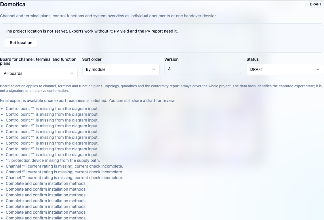
Draft carries a watermark and also works with open data. Final requires export readiness; the interface names the open points and offers Address the next open item. Status, version and data hash are explained in Plan KNX: push buttons, channels and quantities.
How do I agree open points with the team?
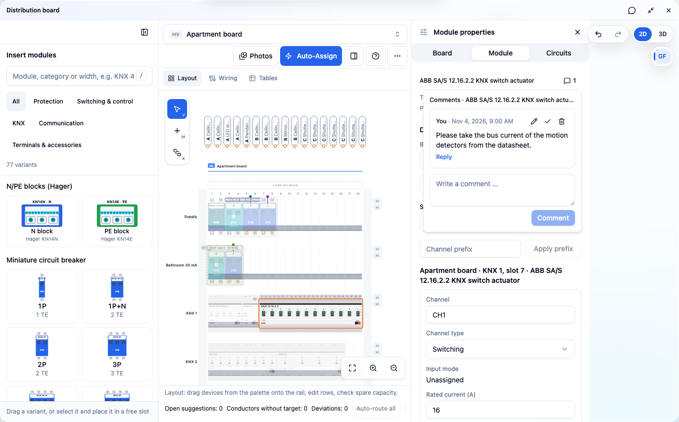
Select a module in the cabinet and, in Module properties, open the speech bubble icon next to the module name. There you write a comment directly on the module, for example about a bus current that still has to come from the datasheet. In the Notes & tasks panel, under Tasks, you create a task and assign it. Approvals of archived documents run through the same area.
KNX only: how does PlanElec propose physical addresses and group addresses?
- In the Channels panel, choose the Addresses view.
- Choose the Group address scheme: Trade / floor / object (default) or Floor / trade / object.
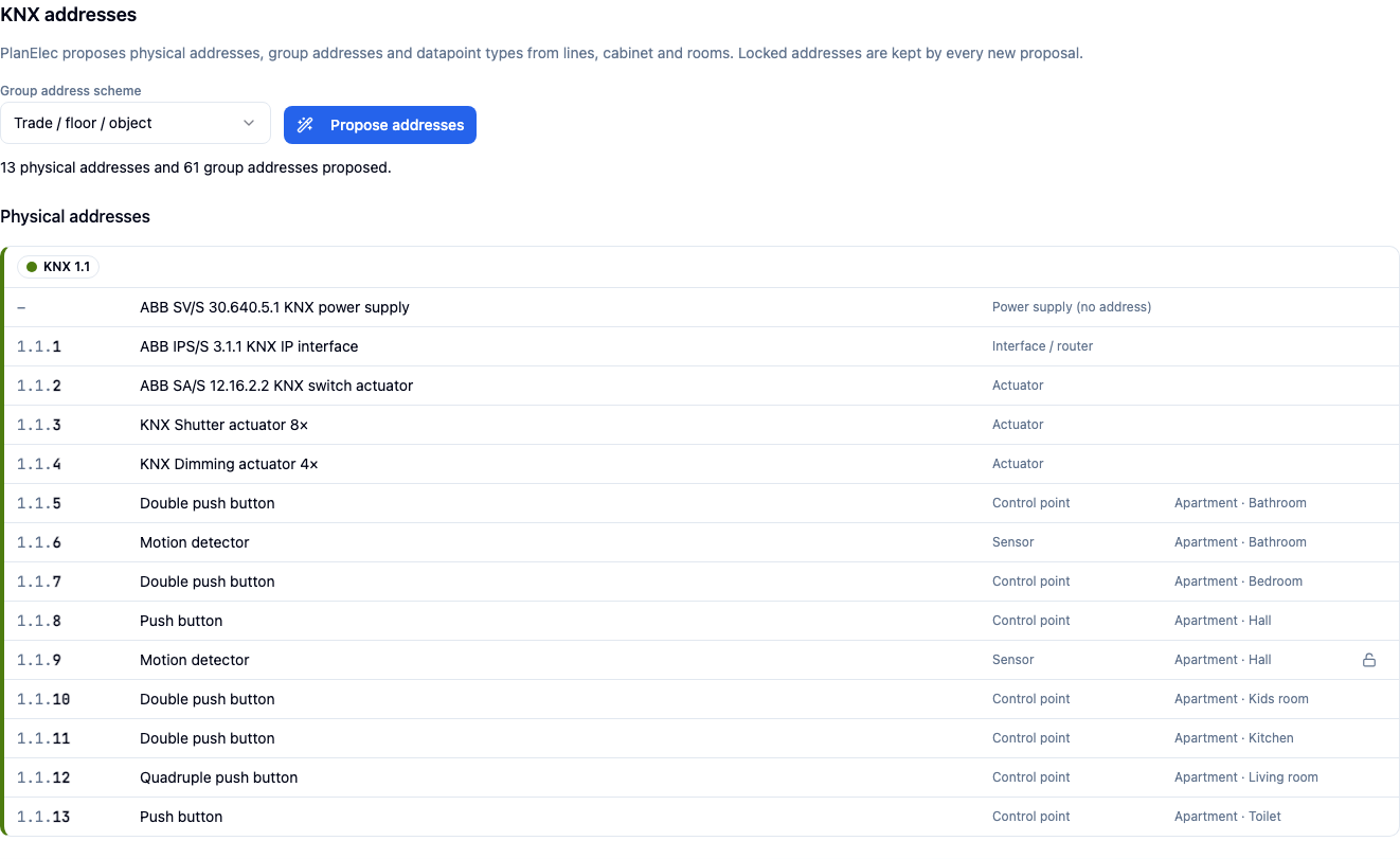
- Click Propose addresses. The line below states the result, in the example “13 physical addresses and 61 group addresses proposed.” The proposal is a single undo step.
| Rule | Proposal |
|---|---|
| Line coupler | x.y.0 |
| Power supply | no physical address |
| Actuators and interfaces | from x.y.1 in cabinet order (board, rail, slot) |
| Bus control points | afterwards, by room |
| Devices without a line | no address; the summary counts them and the check reports them |
Group addresses have three levels: main group, middle group, sub group. In the default scheme the main group is the trade, the middle group the floor (0 without floor) and the sub group the running object number.
| Main group | Trade | Objects and datapoint type (DPT) |
|---|---|---|
| 1 | Lighting | switch 1.001, status 1.001 |
| 2 | Dimming | switch 1.001, relative dimming 3.007, brightness value 5.001, status 1.001 and 5.001 |
| 3 | Blinds | up/down 1.008, stop/slat 1.007, position 5.001, position status 5.001 |
| 4 | Heating | setpoint and actual value 9.001, valve output 5.001, operating mode 20.102 |
| 5 | Inputs | switch object 1.001; detector brightness 9.004 |
| 6 | Scenes | scene 17.001 |
| 7 | Central | switch 1.001 or up/down 1.008 |
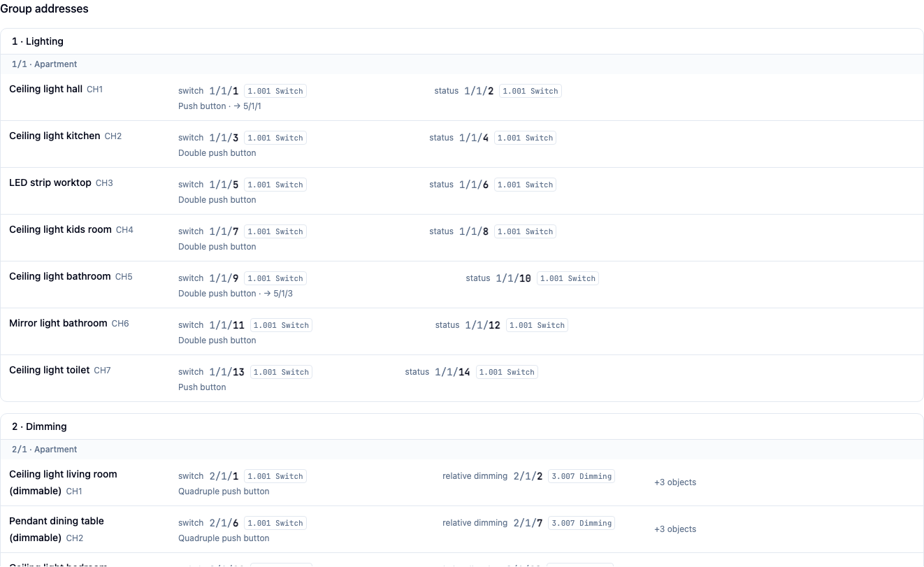
Group addresses are only created for channels with at least one load; a spare channel stays without an address. Each row shows a channel with the name of its load; switching and status sit side by side, each with its datapoint type and name, further objects as “+3 objects”. Clicking an address opens the input field. PlanElec locks a changed address automatically; with the lock (Lock address), which appears on hover, you lock it explicitly. Every further proposal keeps locked addresses, and their numbers are not reassigned. The check reports duplicate or invalid addresses as conflicts.
KNX only: how do I download the addresses as files for ETS?
- In the mode bar on the left, choose Export and scroll to the Domotica section.
- In the ETS preparation box, download Group addresses CSV (ETS), Group addresses XML (ETS) or Physical address list CSV. Without an address proposal, the box tells you to propose addresses first.
- The files follow the ETS group address format. You create devices, parameters and the links to communication objects in ETS; check every address you take over there.

| File | Content |
|---|---|
| Group addresses CSV (ETS) | Format “3/1”: main, middle and sub group, address, description, DPT as DPST-x-y; comma, UTF-8 with BOM |
| Group addresses XML (ETS) | Group address export in the XML schema http://knx.org/xml/ga-export/01 with range names |
| Physical address list CSV | Line, physical address, device, type and room as a working list |
Group addresses carry no link to communication objects. That is why the description of every group address states which buttons, detectors or scene participants use it; you create the link itself in ETS. We have not tested an import against a particular ETS version and do not promise one. The exports do not depend on the dossier release: you can download them while the project is still a draft.
What does PlanElec not do?
| PlanElec does | Stays in the manufacturer's software or on site |
|---|---|
| Plans and documents board, channels, terminals and lines | Programming the devices, parameters and logic |
| Channel, terminal and function plans, topology, quantities, dossier | Wiring on site, single-conductor wiring plan, ordering |
| Bus budget with entered and estimated values | Measuring the bus current, bus diagnostics, commissioning |
| Logical lines and bus cable on the floor plan | Measured cable routes, insulation testing |
| KNX only: address proposal and files in ETS format | ETS project (.knxproj), product databases, communication objects |
| Planning findings and the AREI self-check | Acceptance of the installation by the approved inspection body |
Can the workflow be shown in the Studio?
Yes. In the Learning center, start the Smart home tour. In about three minutes it shows the system, planning steps, Place module, channel table, lines, functions and the documents in the export, for KNX also addresses and ETS preparation, without changing your project. It skips steps whose target is still missing in the project.
Related guides
Important for electrical planning
These guides explain the software workflow. Have the design, installation and documents reviewed by a qualified electrician where needed; only an accredited inspection body performs the official inspection.
Continue reading
Getting started: from a new project to your first PDF
Create a project, choose the floor plan or the single-line diagram as your starting point, use guidance, a template or AI floor plan recognition, and produce your first draft PDF.
Using and reviewing automatic planning
Use PlanElec proposals for devices, switch chains, cable routes, circuits, phases, and the distribution board without skipping technical review.